Here are my notes on a short introduction to networking course from Nvidia. This includes the different components and characteristics of a network, as well as the flow of encapsulation and OSI and TCP/IP models.
Revised on Jan 3, 2026
What is Networking?
A network is a collection of nodes connected to exchange data. This must be why there are so many LeetCode Graphing Problems on networking — they can be simplified down to a graph of connected nodes 🙂
Characteristics of a Network
Networks have the following characteristics:
- Bandwidth
- Latency
- Availability
- Scalability
- Security
These are the characteristics that are important to consider when designing a network.
Network Components
Networks are made up of the following components:
- End Nodes: Devices that are connected to the network. These are used as the source and destination of data.
- Intermediate Nodes: Switches and routers that receive traffic generated by end nodes and make decisions on where that information is going.
Other network components include:
- Network Cloud
- Storage
- Firewall
- Server
- Compute
- Switch
- L3 Switch
- Router
Building a Network
Let’s design a simple network. The first thing we should know is that every end node has a network interface card (NIC). The NIC is a hardware component that resides in a slot and has one or more network ports. A cable connects the NIC in the end point to a switch port.
End point is another term for end node. A switch is a device that connects multiple devices on a network. It operates at the data link layer of the OSI model. OSI stands for Open Systems Interconnection, and will be discussed again in more detail below. It is a conceptual model that standardizes into seven layers the functions of a telecommunication or computing system.
So now that nodes are connected to the network, they need a way to communicate. Nodes use protocols to communicate. Each protocol is responsible for a specific set of activities and defines a comment set of rules and formates to exchange messages between devices. This includes:
- Setup and termination of data transfer sessions
- Message format
- Error and system messages
A protocol suite is a group of protocols that run concurrently to implement network communication.
OSI Model
The Open Systems Interconnection (OSI) model breaks down different components of network communication into layers, makign communication easier. This will make more sense as we break down the layers themselves. OSI is a generic, protocol-independent ISO standard. There are many advantages to using a layered model, a few listed below:
- Standardizes interfaces
- Facilitates modular engineering
- Ensures interoperable technology
- Accelerates evolution - the model can be updated with new technologies easily
Here are the layers of the OSI model
- Physical Layer - Responsible for physical connection between layers.
- Data Link Layer - Responsible for error detection and correction.
- Network Layer - Responsible for routing and forwarding.
- Transport Layer - Responsible for end-to-end communication.
- Session Layer - Responsible for session management.
- Presentation Layer - Responsible for data translation.
- Application Layer - Responsible for user interface.
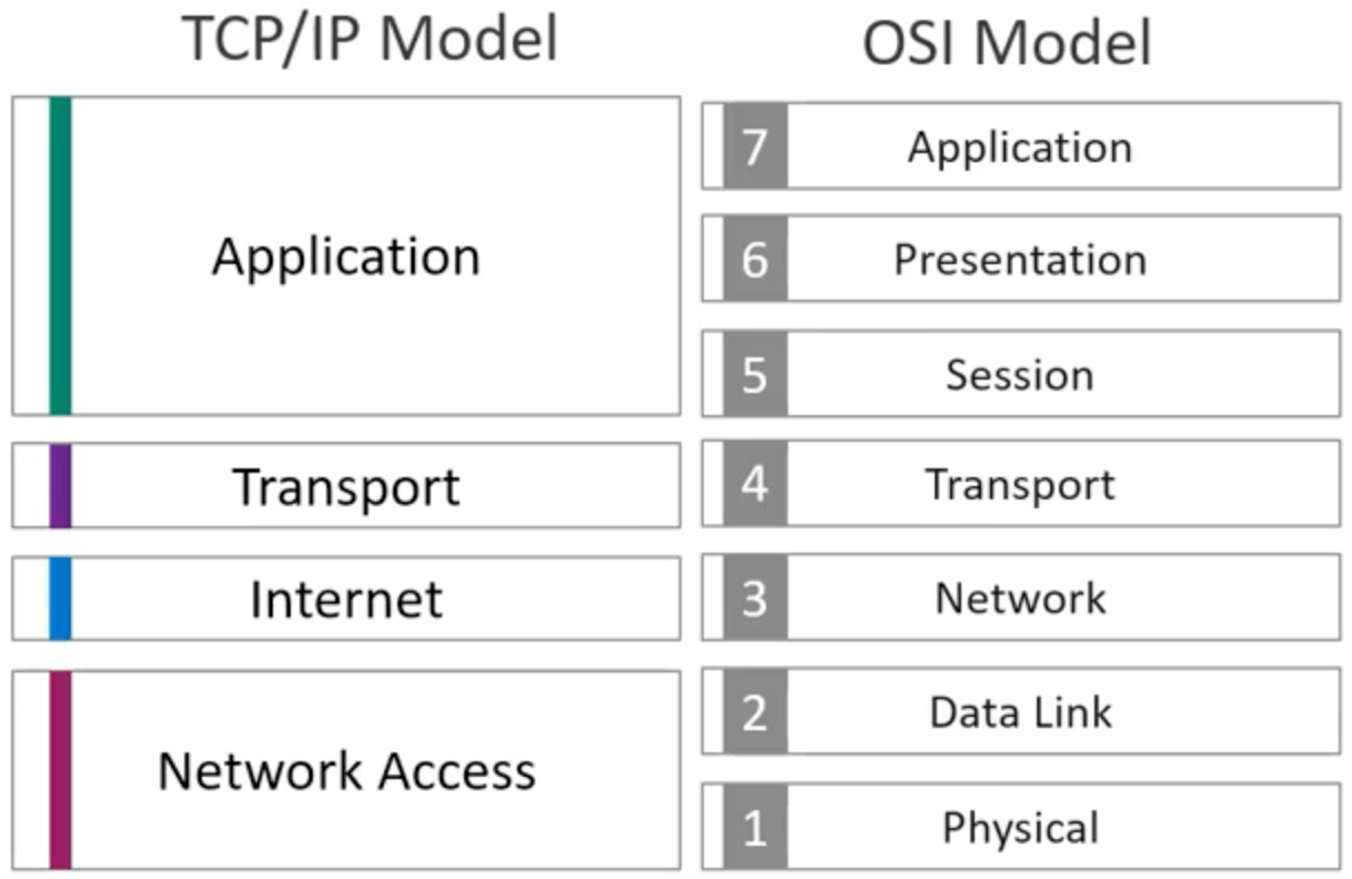
TCP/IP Model
TCP/IP models, in a way, are an implementation of the OSI model, as they are both layered models. The TCP/IP model is a suite of protocols that are used to communicate over the internet. TCP/IP defines how computers should be connected to the internet and how data can be transmitted between them.
The TCP/IP Suite is named after the two main protocols, Transmission Control Protocol and Internet Protocol.
TCP/IP includes protocols for how data should be packetized, addressed, transmitted, routed, and received; therefore, TCP/IP provides end-to-end data communication. Below are some protocols in the TCP/IP suite:
- Link layer (network access) protocols: Ethernet and PPP (layer 2)
- Internet layer protocols: IPv4 and IPv6 (layer 3)
- Transport layer protocols: TCP and UDP (layer 4)
- Application layer protocols: HTTP, FTP, DHCP, and DNS (layer 7)
The TCP/IP model has 4 layers, compared to the 7 layers of the OSI model. These 4 layers are:
- Network Access Layer - Ethernet
- Internet Layer - IPv4 and IPv6
- Transport Layer - TCP and UDP - TCP stands for Transmission Control Protocol and UDP stands for User Datagram Protocol.
- Application Layer - HTTP, FTP, DHCP, and DNS
Although there are only 4 layers, each protocol should refer to the OSI model layer. That is why internet layer protocols, IPv4 and IPv6, are considered to be on layer 3.
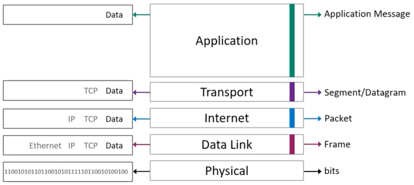
Encapsulation
Application messages (created by the application layer) are passed to a “production line” of the lower layers, where each layer adds its own information by encapsulating the data with the layer header. By the end of the encapsulation process, the encapsulated data is transmitted by the wire.
Let’s go through an example of encapsulation for the TCP/IP model:
- The data generated at the application layer is referred to as a message.
- This message is encapsulated at the lower layer, transport layer. The transport layer adds a layer 4 (transport layer) header that includes fields such as port numbers that are relevant for transport layer processing at the receiving nodes. A message with a layer 4 header is reffered to as a TCP Segment or a UDP Datagram. TCP Segments and UDP Datagrams are the layer 4 PDU (protocol data unit).
- The TCP Segment or UDP Datagram is passed from layer 4 (transport layer) to layer 3 (internet layer), where it is encapsulated with the layer 3 header. The layer 3 (internet layer) header includes information souch as source and destination IP addresses. The layer 3 PDUs (protocol data units) are called packets.
- Packets are routed in the network by layer 3 devices called routers.
- Packets are then passed down from layer 3 (internet layer) to layer 2 (data link layer), and given a layer 2 header. Layer 2 PDUs are called frames. The most important information in the layer 2 header are source and destination MAC addresses.
- Frames are forwarded in the local network by layer 2 devices called switches.
- The frame is then transferred to layer 1, the physical layer, and is converted to a stream of bits.
- The stream of bits is placed on the network medium for transmission.
The resources below will cover more of these terms in more detail, but it is important to at least understand the general flow of encapsulation and the TCP/IP model.
Ethernet
This is a breakdown of how ethernet works, its standards, MTU, and MAC addresses.
What is Ethernet?
Ethernet operates in the data link layer and the physical layer of the OSI model. The data link layer defines functional and procedural means to transfer data between network nodes. The data link layer also detects errors that can occur in the physical layer. The physical layer defines electrical (optical) properties and transfer speed of physical connection between network nodes. Ethernet is the predominant LAN technology, giving high speed performance for a broad range of applications.
Ethernet Addressing
Nodes send Ethernet frames to each other. Ethernet nodes are identified with a unique address known as a MAC (Media Access Control) address. The Ethernet frame header contains source and destination MAC addresses in their header. A network interface card (NIC) is a hardware component that connects nodes to the network. The NIC allows devices to communicate over a network, either by cables or wirelessly. The NIC is both in the physical layer and the data link layer. The NIC provides physical access to the physical medium and provides an addressing system using MAC addresses.
MAC Addresses
The MAC address is the unique identifier assigned to a network interface for use as a network address. A MAC address is burned on the network adapter’s hardware by the vendor. MAC addresses are 48-bit. The left half represents the OUI (Organizationally Unique Identifier) and the right half represents the serial number assigned by the vendor. The MAC address is listed as 12 unique hexidecimal digits.
Ethernet Frame Structure
An Ethernet frame includes the following fields:
- Payload: upper layer protocol data (e.g. IPv4/6 packet)
- Destination MAC Address: specifies the node for which the frame is intended
- Source MAC Address: specifies the node sending the frame
- Length/Type: indicates the upper layer protocol (EtherType)
- FCS: trailer used for the detection of corrupt frames
FCS stands for Frame Check Sequence
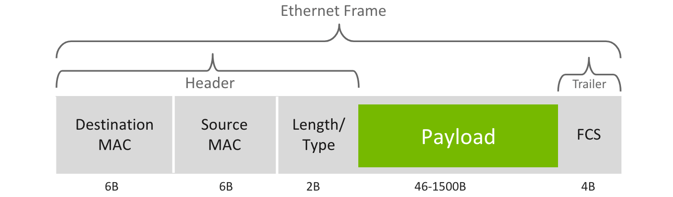
Maximum Trasmit Unit (MTU) defines the maximum payload size that can be carried by a single Ethernet frame. Frames with more than 1500 bytes payload are considered “jumbo frames.” Ethernet frame size is 64-1518 bytes.
Ethernet Switches
An Ethernet switch connects multiple Ethernet nodes. Ethernet nodes may have one or more Ethernet switches connecting between them. An Ethernet switch forwards frames from source to destination. They utilize a MAC Address Table, a database of known MAC addresses mapped to switch (exit) ports. The MAC Address Table is populated by the switch by learning the source MAC address of incoming frames. They are dynamically maintained, and entries are removed after a certain time period.
A unicast frame is a frame sent from one node to another. Frames with destination MAC addresses not found in the MAC Address Table are known as unknown unicast frames. The switch floods the unknown unicast frame, sending it to all other ports besides the incoming port.
A broadcast frame represents all nodes on a network. The address is represented with a destination MAC address with all bits set to 1 (i.e. FF:...:FF in hex). There are also multi-cast frames, which allow one to specify multiple destinations, although are generally flooded to all ports.
Layer 3 Switches
A Layer 3 switch is a switch that operates at the network layer (layer 3). Traditional switches just operate at the data link layer (layer 2). Layer 3 switches can make routing decisions based on IP addresses, therefore giving the capability to act as both a switch and a router.
TCP/IP
This is a breakdown of different protocols in the TCP/IP Protocol Suite. The TCP/IP Protocol Suite is a set of protocols that are used to communicate over the internet. It is the most widely used protocol suite in the world, and is named after the two most important protocols, TCP (Transmission Control Protocol) and IP (Internet Protocol).
Application Layer Protocols
It’s important to remember that the goal a network is to transfer information. For two applications to exchange information over a network, they most implement the same protocol. An example of this is web browsers requesting a web page from a web server. On one end, the application is the web browser. On the other end, the application is the web server.
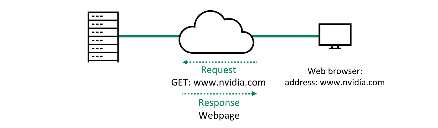
When a user puts a URL address in the address bar of a web browser, the web browser converts the request to a format the web server will be able to understand. The web server will respond with a format that the browser can display in text or links.
Whenever an application wants to communicate with another remote application, it hands over data to the transport layer.
HTTP
HTTP is the Hyper Text Transfer Protocol. HTTP allows the exchange of text and hyperlinks. HTTPS is the secure variant of HTTP. HTTP functions as a request-response protocol in the client-server model. The client submits an HTTP request message to the server. The server will respond with resources (such as HTML files) and a response message including a completion status.
FTP
FTP is the File Transfer Protocol. It is also an application layer protocol. Users can either connect anonymously to the server or sign in with a clear-text sign-in protocol, usually a username and password. FTPS is the secur variant of FTP, encrypting the content and protecting the username and password.
Transport Layer Protocols
The next step is for the application layer protocol to ask for transport layer services. Transport layer protocols establish end-to-end logical communcation channels between applications. They facilitate the communication of hosts. They can provide a reliable connection and carry out error checking, flow control, and verification. Eventually it asks layer 3 (network layer) to carry information to the destination. TCP and UDP operate at the transport layer.
TCP
TCP is the Transmission Control Protocol. TCP is a connection-oriented transfer protocol, meaning a connection is established between the peer entities prior to tranmission. TCP uses sequence numbers and acknowledgements (know as ACKs) to recover damaged or lost data. TCP allows the receiver to govern the amount of data sent by the sender. Sequence numbers are also used to order segments and give ordered delivery.
Generally, applications that require reliability use TCP as their transfer protocol layer. For applications that require fast and light-weight transportation, TCP is not be the best choice.
TCP Sessions
When two application processes wish to communicate over TCP:
- A connection must be established
- Data can now be transfered
- TCP uses a keep-alive feature to manage connections
- After data transmission is completed, the connection is terminated and all allocated resources are released.
Three-Way Handshake
TCP connections are established using the three-way handshake process:
- Client sends a syncronization (SYN) message to the server. The goal of this message is to ask the server if it is open for connections.
- The server must return an acknowledgement (ACK) message. SYN and ACK are flags in the TCP header, also known as control bits.
- Client responds with its own ACK message.
- Connection is now created and the client and server can communicate.
UDP
UDP is the User Datagram Protocol. UDP allows applications to communicate with a minimum protocol overhead. For UDP, data is continuously sent, rather the recipient is ready for it or not. Unlike TCP, UDP is connectionless, meaning no session is established. UDP uses no ACKs, and therefore has no re-transmissions, flow control or re-delivery. On the other hand, UDP is much more resource efficient and uses less bandwidth.
Bandwith is the maximum amount of bits that can be transmitted between two applications in a given time period. When we say UDP uses less bandwidth, it means it takes less bits to transfer the same information.
Port Numbers
Both UDP and TCP use source and destination port numbers to identify specific processes or service within local and remote nodes. For example, the default port for HTTP is 80. A client may request an HTTP service and would therefore specify 80 as the destination port.
Network (Internet) Layer Protocols
Now that our application layer message has passed through the transport layer, UDP or TCP, it is time to move onto the network (or internet) layer protocols, layer 3.
IP
IP is the internet protocol and operates on the network layer. IP provides services to layer 4 protocols and asks layer 2 protocols to carry the IP packets. IP is a best-effort protocol and therefore does not include mechanisms for reliability, flow-control, and sequencing.
Unlike UDP and TCP who communicate directly between applications, IP provides the functions necessary to deliver a packet from source to destination over an interconnected system of networks.
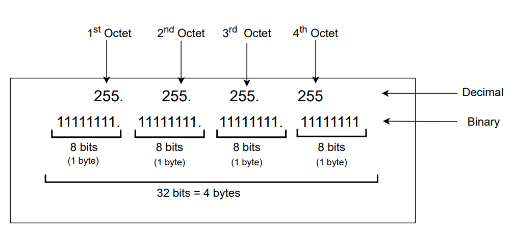
IPv4 Addressing
Today, IP has two main versions, IPv4 and IPv6. IPv6 is the newest version. An IP address is assigned to a network interface of node. IPv4 addresses are 32 bits (4 octets). Each octet is separated by a dot and shown as its decimal equivalent.
IP addresses have two parts:
- Network Address: identifies the network portion of the address
- Host Address: identifies a specific host within a network
All hosts in the same subnet share the same common subnet address. Every router interfact defines an IP subnet.
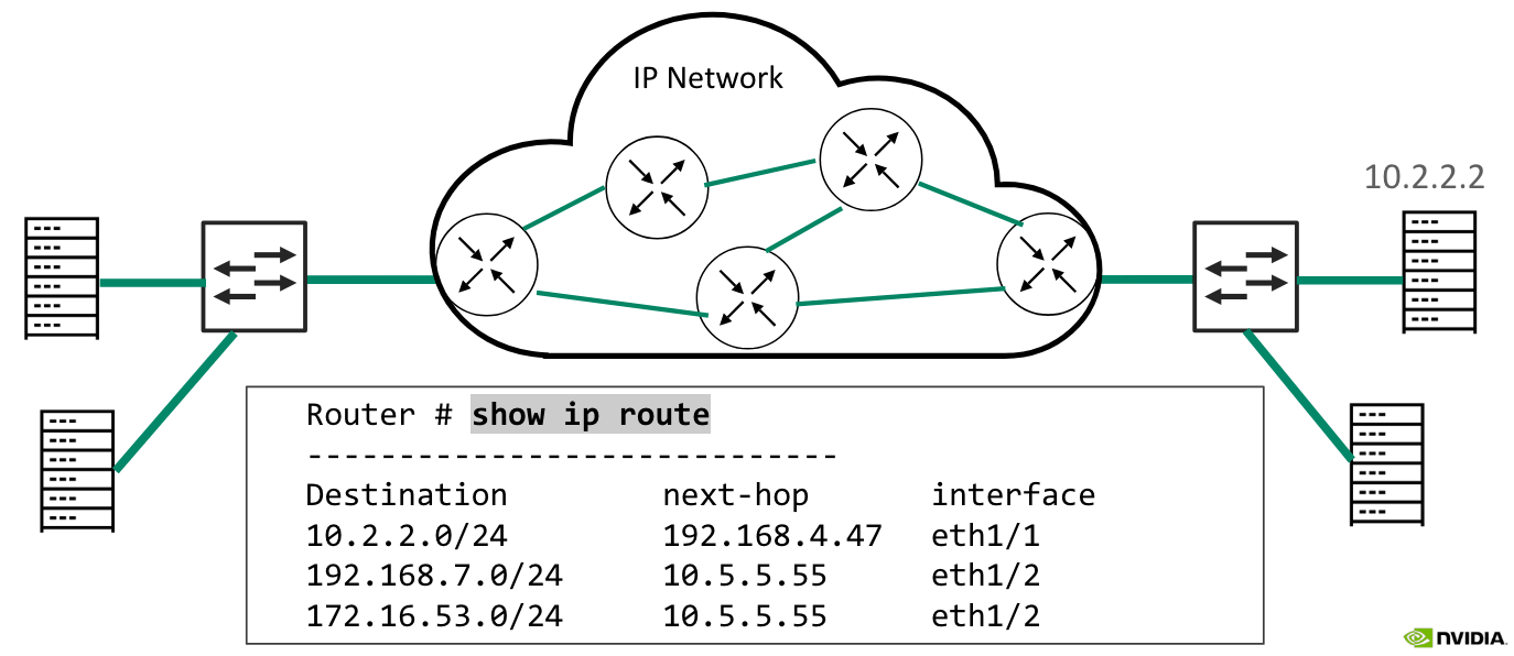
IP Routers
Routing is the process of choosing the best path to reach the destination. This must be why there are so many LeetCode Graphing Problems on networking 🙂
A router is a computer that has been dedicated to the task of forwarding IP packets between networks. A router makes forwarding decisions based on its forwarding database, called a routing table. A routing table includes entries that map remote IP networks to next-hop routers that are identified by local interfaces. The router will forward the packet to the next-hop router, until the packet reaches the destination, hop by hop.